Sensors
The sensors' bundle provides the ability to quickly attach sensors to models to provide realistic observations of the environment. Each sensor in this bundle models the sensor logic, the functional essence of the sensor, separately from its physical body. This allows sensor logic to be attached to any suitable physical attachment that one would wish to use.
- Structure
- Lidars
- Pulsed Lidars
- Sensing Distortions for Lidars
- Cameras
- Camera Lenses
- Digital CMOS Sensors
- Active Illumination
- Color Images
- Color Video
- Depth Images
- Depth Video
Structure
The structure of the sensors' bundle consists of a main root directory where all base sensor logics reside, an Optics directory containing component models and traits for various optical aspects and a Signals directory containing all input and output definitions for the sensors.
Lidars
Light detection and ranging (Lidar) is a kind of sensor that is generally used to scan an environment into a point cloud, providing a 3D representation of the environment. The sensors' bundle provides a simple way to model lidar sensors.
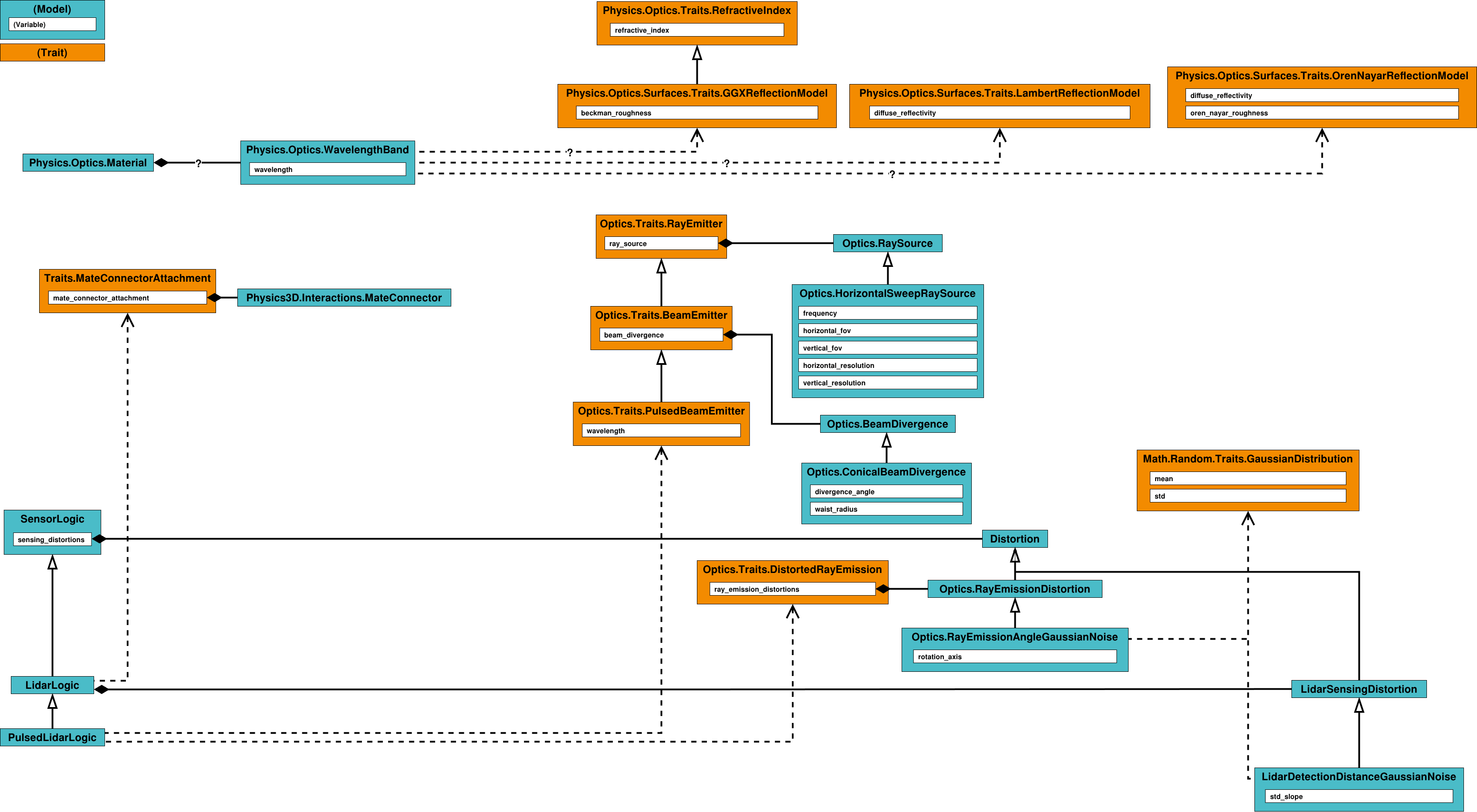
Pulsed Lidars
For the most common case of a pulsed lidar sensor, the Sensors.PulsedLidarLogic can be added to a Physics3D.System, which can then be provided with a suitable body to which the logic can be connected through a Physics3D.Interactions.MateConnector:
MyPulsedLidar is Physics3D.System:
    body is Physics3D.Bodies.RigidBody:
        is_dynamic: false
        inertia:
            mass: 1.0
            tensor: Physics3D.Bodies.Inertia.symmetric_tensor(Math.Vec3.from_xyz(1.0, 1.0, 1.0), 0.0, 0.0, 0.0)
        visual is Visuals.Geometries.Cylinder:
            local_transform:
                rotation: Math.Quat.from_euler_angles(Math.Functions.deg_to_rad(90.0), 0.0, 0.0)
            radius: 0.05
            height: 0.1
        connector is Physics3D.Interactions.MateConnector

    logic is Sensors.PulsedLidarLogic:
        wavelength: 905e-9
        mate_connector_attachment: body.connector
        beam_divergence: ?
        ray_source: ?
To make a properly functioning pulsed lidar, one must also specify a ray emission source, configuring the ray emission properties, and a configuration of the divergence of the emitted beams.
Alternatives for these can be found in the Sensors.Optics subdirectory, and added to the pulsed lidar logic:
MyPulsedLidar is Physics3D.System:
    ⋮
    logic is Sensors.PulsedLidarLogic:
        ⋮
        beam_divergence becomes Sensors.Optics.ConicalBeamDivergence:
            divergence_angle: 0.1
            waist_radius: 0.0
        ray_source becomes Sensors.Optics.HorizontalSweepRaySource:
            frequency: 60.0
            horizontal_fov:
                x: 0.0
                y: Math.Functions.deg_to_rad(360.0)
            vertical_fov:
                x: Math.Functions.deg_to_rad(-15.0)
                y: Math.Functions.deg_to_rad( 15.0)
            horizontal_resolution: 1024
            vertical_resolution: 64
With this, the basic logic of a rotary pulsed lidar has been created.
Then, to access the produced point cloud in a generic way a Sensors.Signals.LidarOutput is added to the logic with the output fields of interest specified.
A position and intensity output is added as:
MyPulsedLidar is Physics3D.System:
    ⋮
    logic is Sensors.PulsedLidarLogic:
        ⋮
        my_output is Sensors.Signals.LidarOutput:
            type: 0
            fields: [
                Sensors.Signals.LidarOutputField.Position3D_F32,
                Sensors.Signals.LidarOutputField.Intensity_F32,
            ]
            source: logic
This configuration currently denotes a ground truth rotary pulsed lidar.
Optionally, to distort the rays emitted from the lidar a number of Sensors.Optics.RayEmissionDistortion specializations can be added to the ray_emission_distortions array in the lidar logic.
Alternatives for these can be found in the Sensors.Optics subdirectory, and added as:
MyPulsedLidar is Physics3D.System:
    ⋮
    logic is Sensors.PulsedLidarLogic:
        ⋮
        my_angle_distortion is Sensors.Optics.RayEmissionAngleGaussianNoise:
            mean: 0.0
            standard_deviation: 0.1e-3
            rotation_axis: Math.Vec3.X_AXIS()

        ray_emission_distortions: [ logic.my_angle_distortion ]
Sensing Distortions for Lidars
Optionally, to add distortions to the sensing process, light detection and post-processing, of the lidar sensor specializations of Sensors.LidarSensingDistortion can be added to the sensing_distortions array of the lidar.
Alternatives for these can be found in the root Sensors directory of the bundle, and added as:
MyLidar is Physics3D.System:
    ⋮
    logic is Sensors.LidarLogic:
        ⋮
        my_detection_distance_error is Sensors.LidarDetectionDistanceGaussianNoise:
            mean: 0.0
            standard_deviation: 0.5e-2
            standard_deviation_slope: 0.4e-4

        sensing_distortions: [ logic.my_detection_distance_error ]
Cameras
A camera is a kind of sensor that is generally used to capture images of a 3D environment. The sensors' bundle provides a simple way to model camera sensors.
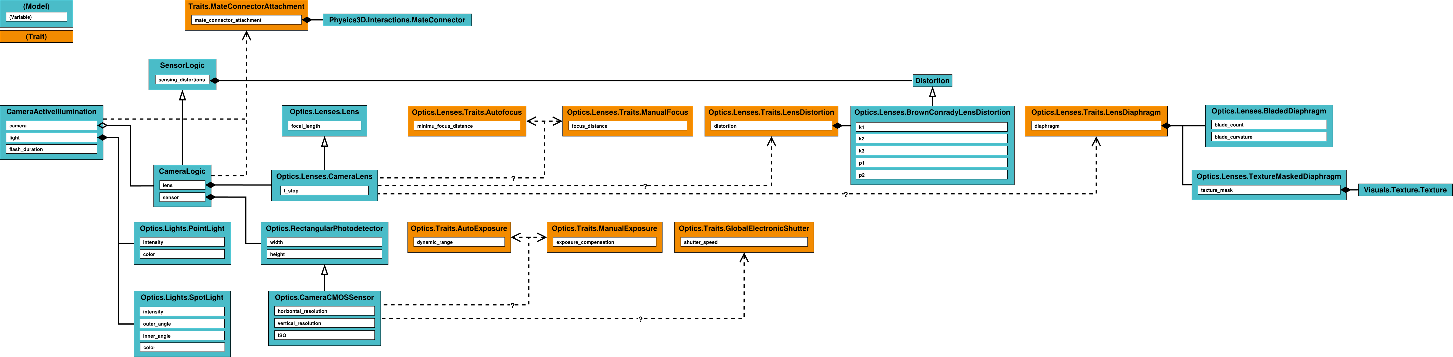
Generally, a camera is built through a Sensors.CameraLogic.
This Sensors.CameraLogic can be added to a Physics3D.System, which can then be provided with a suitable body to which the logic can be connected through a Physics3D.Interactions.MateConnector:
MyCamera is Physics3D.System:
    body is Physics3D.Bodies.RigidBody:
        is_dynamic: false
        inertia:
            mass: 1.0
            tensor: Physics3D.Bodies.Inertia.symmetric_tensor(Math.Vec3.from_xyz(1.0, 1.0, 1.0), 0.0, 0.0, 0.0)
        visual is Visuals.Geometries.Cylinder:
            local_transform:
                rotation: Math.Quat.from_euler_angles(Math.Functions.deg_to_rad(90.0), 0.0, 0.0)
            radius: 0.05
            height: 0.1
        connector is Physics3D.Interactions.MateConnector

    logic is Sensors.CameraLogic:
        mate_connector_attachment: body.connector
        lens: ?
        sensor: ?
Camera Lenses
For most cameras, the general workings of the lens system can then be approximated by a single lens element using a Sensors.Optics.Lenses.CameraLens:
MyCamera is Physics3D.System:
    ⋮
    logic is Sensors.CameraLogic:
        ⋮
        lens becomes Sensors.Optics.Lenses.CameraLens:
            focal_length: 3.0e-3
            f_stop: 2.0
The lens focus mode can be chosen either through a manually set focus distance:
MyCamera is Physics3D.System:
    ⋮
    logic is Sensors.CameraLogic:
        ⋮
        lens becomes Sensors.Optics.Lenses.CameraLens with Sensors.Optics.Lenses.Traits.ManualFocus:
            ⋮
            focus_distance: 2.0
Or by using autofocus:
MyCamera is Physics3D.System:
    ⋮
    logic is Sensors.CameraLogic:
        ⋮
        lens becomes Sensors.Optics.Lenses.CameraLens with Sensors.Optics.Lenses.Traits.Autofocus:
            ⋮
            minimum_focus_distance: 1.0e-2
Realistically, lenses also tend to produce a distorted image.
This can be achieved by adding a Sensors.Optics.Lenses.Trats.LensDistortion to the Sensors.Optics.Lenses.CameraLens, providing a five-parameter Brown-Conrady distortion:
MyCamera is Physics3D.System:
    ⋮
    logic is Sensors.CameraLogic:
        ⋮
        lens becomes Sensors.Optics.Lenses.CameraLens with …, Sensors.Optics.Lenses.Traits.LensDistortion:
            ⋮
            distortion:
                k1: 0.08
                k2: 0.005
                k3: 0.0
                p1: 0.0
                p2: 0.0
A diaphragm can optionally be added to the lens system through the Sensors.Optics.Lenses.Traits.LensDiaphragm trait, and specialized to either a Sensors.Optics.Lenses.TextureMaskedDiaphragm or a Sensors.Optics.Lenses.BladedDiaphragm:
MyCamera is Physics3D.System:
    ⋮
    logic is Sensors.CameraLogic:
        ⋮
        lens becomes Sensors.Optics.Lenses.CameraLens with …, Sensors.Optics.Lenses.Traits.LensDiaphragm:
            ⋮
            diaphragm becomes Sensors.Optics.Lenses.BladedDiaphragm:
                blade_count: 8
                blade_curvature: 0.0
Digital CMOS Sensors
The camera sensor can then be specified as a CMOS sensor, making this a digital camera:
MyCamera is Physics3D.System:
    ⋮
    logic is Sensors.CameraLogic:
        ⋮
        sensor becomes Sensors.Optics.CameraCMOSSensor:
            width: 8.6e-3
            height: 5.0e-3
            horizontal_resolution: 2133
            vertical_resolution: 1200
            ISO: 100
A global electronic shutter can then be added to this sensor:
MyCamera is Physics3D.System:
    ⋮
    logic is Sensors.CameraLogic:
        ⋮
        sensor becomes Sensors.Optics.CameraCMOSSensor with Sensors.Optics.Traits.GlobalElectronicShutter:
            ⋮
            shutter_speed: 10.0e-3
The exposure settings are then defined similarly to the lens focus settings as either through a manually set exposure compensation value:
MyCamera is Physics3D.System:
    ⋮
    logic is Sensors.CameraLogic:
        ⋮
        sensor becomes Sensors.Optics.CameraCMOSSensor with …, Sensors.Optics.Traits.ManualExposure:
            ⋮
            exposure_compensation: -5.0
Or through automatic exposure compensation based on dynamic range:
MyCamera is Physics3D.System:
    ⋮
    logic is Sensors.CameraLogic:
        ⋮
        sensor becomes Sensors.Optics.CameraCMOSSensor with …, Sensors.Optics.Traits.AutoExposure:
            ⋮
            dynamic_range: 5.0
Active Illumination
Some cameras have a source of active illumination, such as a flash. Active illumination sources local to a camera can be specified by adding instances of Sensors.CameraActiveillumination to the camera system, tying them to the camera and, most commonly, connecting them in relation to the camera body:
MyCamera is Physics3D.System:
    ⋮
    body is Physics3D.Bodies.RigidBody:
        ⋮
        illumination_connector is Physics3D.Interactions.MateConnector:
            position: Math.Vec3.from_xyz(0.0, 4.0e-3, 3.0e-3)

    logic is Sensors.CameraLogic:
        ⋮

    illumination is Sensors.CameraActiveIllumination:
        camera: logic
        mate_connector_attachment: body.illumination_connector
        light becomes ??: ??
        flash_duration: logic.sensor.shutter_speed * 0.5
The active illumination light source can then be specialized as either a Sensors.Optics.Lights.PointLight or a Sensors.Optics.Lights.Spotlight:
MyCamera is Physics3D.System:
    ⋮
    body is Physics3D.Bodies.RigidBody:
        ⋮
        illumination_connector is Physics3D.Interactions.MateConnector:
            position: Math.Vec3.from_xyz(0.0, 4.0e-3, 3.0e-3)

    logic is Sensors.CameraLogic:
        ⋮

    illumination is Sensors.CameraActiveIllumination:
        ⋮
        light becomes Sensors.Optics.Lights.Spotlight:
            intensity: 1.0e4
            outer_angle: Math.Functions.deg_to_rad(15.0)
        ⋮
Color Images
To capture color images, a Sensors.Signals.CameraColorOutput is added to the Sensors.CameraLogic:
MyCamera is Physics3D.System:
    ⋮
    logic is Sensors.CameraLogic:
        ⋮
        color_output is Sensors.Signals.CameraColorOutput:
            horizontal_resolution: 320
            vertical_resolution: 240
            source: logic
Optionally, the channel value types can be changed to any value listed in Sensors.Signals.CameraOutputChannelType:
MyCamera is Physics3D.System:
    ⋮
    logic is Sensors.CameraLogic:
        ⋮
        color_output is Sensors.Signals.CameraColorOutput:
            ⋮
            channel_type: CameraOutputChannelType.F32
And the channel mapping matrix can be changed to linearly recombine the output values:
MyCamera is Physics3D.System:
    ⋮
    logic is Sensors.CameraLogic:
        ⋮
        color_output is Sensors.Signals.CameraColorOutput:
            ⋮
            matrix: CameraColorOutputMatrices.BGR_OUTPUT
Additionally, the trait Sensors.Signals.Traits.RelativeIlluminanceCutoff can be assigned to the output to cause the pixel values to be invalidated if the captured post-exposure relative RGB illuminance falls outside the open range specified:
MyCamera is Physics3D.System:
    ⋮
    logic is Sensors.CameraLogic:
        ⋮
        color_output is Sensors.Signals.CameraColorOutput with Sensors.Signals.Traits.RelativeIlluminanceCutoff:
            ⋮
            minimum_relative_illuminance: 0.4
            maximum_relative_illuminance: Math.INF
To actually tell the input to capture during runtime, a signal is sent to the Sensors.Signals.CameraCaptureInput in the output, or to a global Sensors.Signals.CameraCaptureInput attached to the entire camera:
MyCamera is Physics3D.System:
    ⋮
    logic is Sensors.CameraLogic:
        ⋮
        capture_all is CameraCaptureInput:
            source: logic
Color Video
A color video output is configured in the same way as Color Images, except that the capture happens automatically at a framerate as defined by setting the framerate field:
MyCamera is Physics3D.System:
    ⋮
    logic is Sensors.CameraLogic:
        ⋮
        color_output is Sensors.Signals.CameraColorOutput:
            ⋮
            framerate: 30.0
Depth Images
To capture depth images, a Sensors.Signals.CameraDepthOutput is added to the Sensors.CameraLogic:
MyCamera is Physics3D.System:
    ⋮
    logic is Sensors.CameraLogic:
        ⋮
        depth_output is Sensors.Signals.CameraDepthOutput:
            horizontal_resolution: 320
            vertical_resolution: 240
            source: logic
This will generally represent a monocular depth output, like that of a time-of-flight camera.
To change the scaling of the output depth the depth_unit value can be assigned, to for example change the output depth from meters to mm:
MyCamera is Physics3D.System:
    ⋮
    logic is Sensors.CameraLogic:
        ⋮
        depth_output is Sensors.Signals.CameraDepthOutput:
            ⋮
            depth_unit: 1.0e-3
Optionally, the channel value types can be changed to any value listed in Sensors.Signals.CameraOutputChannelType:
MyCamera is Physics3D.System:
    ⋮
    logic is Sensors.CameraLogic:
        ⋮
        depth_output is Sensors.Signals.CameraDepthOutput:
            ⋮
            channel_type: CameraOutputChannelType.F32
Additionally, the trait Sensors.Signals.Traits.RelativeIlluminanceCutoff can be assigned to the output to cause the pixel values to be invalidated if the captured post-exposure relative RGB illuminance falls outside the open range specified:
MyCamera is Physics3D.System:
    ⋮
    logic is Sensors.CameraLogic:
        ⋮
        depth_output is Sensors.Signals.CameraDepthOutput with Sensors.Signals.Traits.RelativeIlluminanceCutoff:
            ⋮
            minimum_relative_illuminance: 0.4
            maximum_relative_illuminance: Math.INF
To actually tell the input to capture during runtime, a signal is sent to the Sensors.Signals.CameraCaptureInput in the output, or to a global Sensors.Signals.CameraCaptureInput attached to the entire camera:
MyCamera is Physics3D.System:
    ⋮
    logic is Sensors.CameraLogic:
        ⋮
        capture_all is CameraCaptureInput:
            source: logic
Depth Video
A depth video output is configured in the same way as Depth Images, except that the capture happens automatically at a framerate as defined by setting the framerate field:
MyCamera is Physics3D.System:
    ⋮
    logic is Sensors.CameraLogic:
        ⋮
        depth_output is Sensors.Signals.CameraDepthOutput:
            ⋮
            framerate: 30.0